Application Aerospace Joining Processes
Challenge-
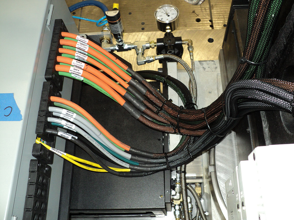
The F35 Landing gear boring system scope of work included the design & build the control system to work on mobile carts with quick disconnects for interchanging between the 1st and 2nd systems.
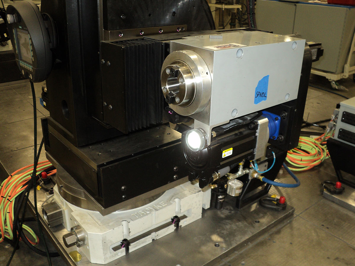
Cycles for Boring, Chamfer, Spot Face, Back Spot Face for CTOL, STOVL & CV Variants with precision tolerances held to thousandths 0.001.
Provide an automated tool that will feel familiar to machinists performing operations.
Strategy-
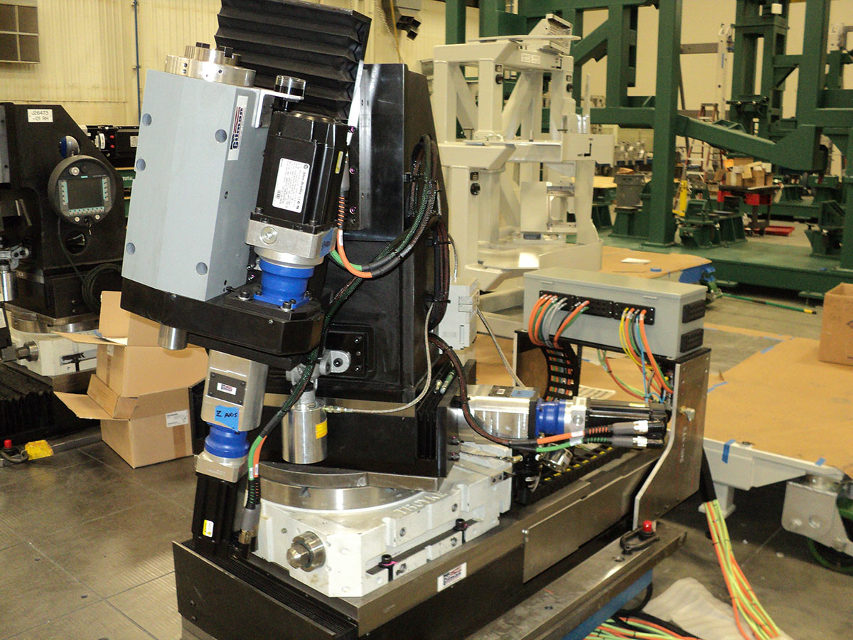
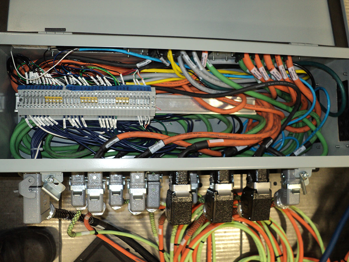
These tools were designed utilizing an Allen Bradley Control Logix PLC with a Kinetics Servo Drive System. The Drag Brace System consists of (12) Servo Drives & Motors, and the Shear Web consists of (12) Servo Drives and Motors. Each system equipped with its own Control Logix PLC for system control and will be capable of running each side simultaneously. If one side shall fault, the other side will run without interference. Each Drag Brace & Shear Web System has two operator pendants, (1) left hand & (1) right hand. Each system is equipped with a large banner HMI display for both left and right hand sides of the tool.
Each tool has a teachable path similar to a robot allowing pathing into tight interference points vectored into landing gear utilizing handwheels providing functionality similar to a CNC making operation familiar to Machinists performing operations.
Results-
A tool that operators find intuitive and easy to use leading to repeat orders for duplicate tools that were built, installed, and commissioned at different manufacturing locations.